Company Logo
  • Products / Services
  • CO₂ Reduction
  • Glass
  • Aluminium and Alumina
  • Copper
  • Boiler
  • Cement & Minerals
  • Chemical
  • Hydrocarbon
  • Incinerator
  • Nonferrous Metals
  • Steel
  • Refractory
  • Other Industries...
  • Equipments
  • HV-1500
  • HV-3000
  • HVO-3600
  • Six Way Console
  • Water Recycling System
  • About Us
  • History
  • CEO Message
  • Meet the Team
  • Legal Notice
  • Privacy Policy
  • Home
  • Downloads
  • References
  • Contact Us
  1. Home
  2. Products & Services
  3. Glass
  4. Cross Fired Furnace
  5. Thermal Regenerator Cleaning

Thermal Regenerator Cleaning

Thermal Regenerator Image One

A clean regenerator operates more efficiently, optimizing the overall performance of your industrial processes.

  • So that the furnace can «breathe» again
  • To reduce fuel costs
  • To avoid the need for an unscheduled furnace repair
Download Flyer

The problem of blocked regenerators is not new in the glass industry, in fact it has been accommodated in regenerator design over many years by building the passage dimensions fairly large and by building more of them than necessary to permit the flow of gases under natural draught conditions.

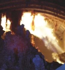
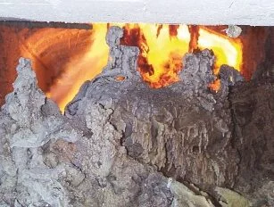
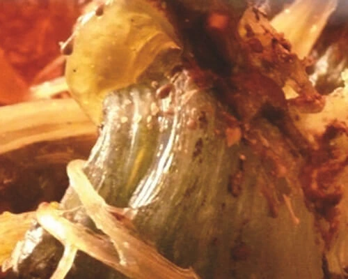
It was generally understood that a regenerator was built twice the size necessary so that, as it gradually became blocked, the furnace would continue to function. The principal cause of regenerator blockage is the condensation of sulphates in the checker work.

The sulphates either come from the fuel, batch or additives to help melting the glass. The carry over from batch materials are also responsible for regenerator blockage. These materials have much higher melting points and are much difficult to remove by thermal cleaning. However, in most cases batch particles are stuck to the sulphates and will run down the regenerator once these start melting.

Thermal Regenerator Image Two
Thermal Regenerator Image Three
Thermal Regenerator Image Four

The HWI Method

The method consists, briefly, of installing a service burner in the bottom of the regenerator chamber and gradually increasing the temperature. The maximum permissible temperature limit is set in consultation with the customer with due regard to the refractory materials (normally the rider arches influence the limit). By appr. 850°C the sulphates begin to melt and run down to the bottom of the regenerators, where they can be caught in a sand pit, and removed from there after resolidification. This operation can be carried out on several chambers, simultaneously or consecutively, without interrupting production.

NOTE:

This method has been successfully carried out on hundreds of regenerative furnaces

When the clogging of the regenerator is not due primarily to sulphates, or if the checker work has failed or in case of any other repair to the regenerator which is needed:

  • HWI burners can be used to hold the furnace temperature while checkers are replaced or the repair has taken place
  • HWI burners can be used for a controlled cool down and consequent heat-up after the repair of the damaged regenerator
Thermal Regenerator Image Five
Thermal Regenerator Image Six

Hotwork International Thailand

96 Soi Vorapong
Samsen Rd.,Banpanthom 
Pranakorn, Bangkok 10200
contact@hotwork.co.th+66 81 803 5995

Hotwork Group

  • Hotwork Holding AG
  • Hotwork International AG
  • Hotwork International Inc.
  • Hotwork - XiX Ltd
  • MPOT Hotwork Solution Ltd
  • IRSP Ltd
  • Hotwork Heat Treatment & Specialized Services Ltd.
  • Heat Up Latin America S. DE R.L. DE C.V
  • PT Hotwork International Indonesia
  • Heat Applications India Ltd.
  • Heat Applications Global Ltd.
  • Total Project Management Ltd.
  • Hotwork International South America S.A.,
  • Hotwork International Co. Ltd. (Thailand)
Company Logo  Footer

Copyright © 2025 Hotwork International Thailand  |

This website uses cookies to ensure you get the best experience on it. By using this website, you agree to the cookies terms.

Read more.Dismiss